Tel.: +86 13358378970
E-mail: sales6@saulplc.com

Tel.: +86 13358378970
E-mail: sales6@saulplc.com
Aug. 11, 2023
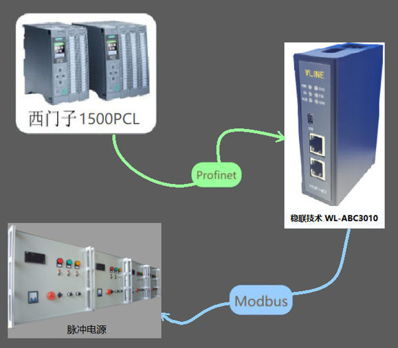
This case is a configuration case where a Modbus TCP to profinet gateway is connected to a pulse power supply. The equipment used is a Siemens 1500PLC, a stable connection technology Modbus TCP to Profinet gateway, and a pulse power supply.

1. Firstly, open the Botu software and create a new project file;
2. Import the GSD file. Copy the GSD file from MODBUS to PROFINET gateway to any location. Open Botu to create a new project. Enter the device and network, select Manage General Station Description File from the options, and install the GSD file.
3. Search for the GSD file storage folder, select Install after searching for GSD, and wait for the installation to succeed.
4. Choose to configure the matching device in Siemens Botu or STEP7
5. Click 'not connected' to connect the IO controller PLC_ 1 PROFINET port_ one
6. After connecting the PLC with the ModbusTCP to Profinet gateway, it is necessary to modify the IP address and PROFINET name of the ModbusTCP to Profinet gateway. Please note that the PROFINET device name option should not be checked for automatic generation, and a new name input must be customized;
7. Double click on the ModbusTCP to Profinet gateway module, add Input and Output through the right module, and finally download the configuration to the PLC;
8. Operate the GATEWAY CONFIGURING STUDIO configuration software and open GATEWAY CONFIGURING STUDIO:
9. Open the ModbusTCP to Profinet gateway configuration software for modbus parameter configuration, click on "New" in the red circle, and select PN2MTC (MODBUS TCP master);
10. Set the PROFINET IP address and device name of the ModbusTCP to Profinet gateway to be consistent with the PLC configuration;
11. Continue to right-click on Insert and insert Node;
12. Modify the MODBUS TCP end (ModbusTCP to Profinet gateway LAN port IP address), and the IP address should be the same as any address in the network segment. The ModbusTCP to Profinet gateway address is set to any address in the same network segment and does not conflict with other addresses.
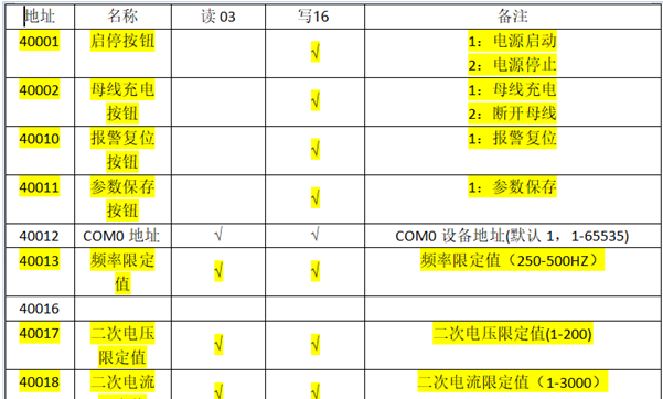
13. Configure in the configuration software according to the pulse power function table

14. Adding function codes includes reading 03 function codes and writing 16 function codes;
15. The address 40001 in the red box corresponds to the starting address 1 of the configuration software; Function code 3; Read 9 registers (the memory mapping address starts from 0, corresponding to the first bit of the I address configured for the Botu ModbusTCP to Profinet gateway.) The address 40017 in the red box corresponds to the starting address 17 of the configuration software; Function code 16; Read 30 registers (memory mapping address starting from 1500, corresponding to the first bit of Q address configured for Botu ModbusTCP to Profinet gateway)
Navigation
Add.: 9D, 9th Floor, Huguang Building, Hubin West Road, Siming District, Xiamen City, Fujian Province, China
Tel.: +86 13358378970
Mob.: +86 13358378970
E-mail: sales6@saulplc.com
WhatsApp: +86 13358378970
Wechat: +86 13358378970